724
Dental and orthodontic techniques are constantly evolving. Problems that seemed insoluble a few years ago can be easily overcome with modern treatment methods.
One of these solutions was the use of a hip plane analyzer when forming jaw prostheses.
General introduction and purpose of the study
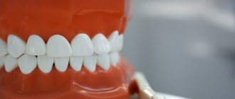
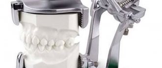
As current dental technicians know, the position of the upper jaw is transferred to the articulator when creating dentures.
Often, patients experience facial asymmetry. This complicates the creation of smooth and comfortable prosthetic structures.
Several measurement options have been created for this purpose.
Frankfurt technique
To facilitate the determination of the correct maxillary position, the Frankfurt plane was proposed in Monaco at the beginning of the 20th century.
The measurement is taken through the lower edge of the orbit to the upper level of the external auditory canal with the head in the correct position.
The technique has come to be considered the main guideline in orthostomatology. This principle is used when measuring with a facebow.
However, as experience has shown, this measurement method is not sufficiently accurate.
Indications and contraindications for orthodontic teeth traction and devices used.
Let's look at the best devices for molar distalization here.
At this address https://www.vash-dentist.ru/ortodontiya/prikus/formirovanie-postoyannogo.html read about the features of the formation of a permanent bite.
Kamperovskaya
The creator of the Kamper plane was Peter Kamper. His work was based on the assertion that the horizontal facial line passes through the lower border of the alar bones and the upper part of the tragus (ear tragus).
This measurement system is adopted in many countries. Using the Camper plane, measurements are taken to create complete dentures for edentulous patients.
Camper's theory works in orthopedic dentistry, but has not found recognition in orthodontic and therapeutic dentistry.
According to many practicing dentists, neither the Frankfurt nor the Camper methods have sufficient reliability.
This is due to the fact that the measurements are not based on the structure of the skull and the definition of bone structures, but on skin areas.
Hip plane analyzer
Another measurement device is the hip plane analyzer, or Shestopalov apparatus. The device is named after its creator, Sergei Ivanovich Shestopalov, an orthopedic dentist with more than 30 years of experience.
The device was designed to accurately measure the position of the upper jaw using measurements directly inside the oral cavity.
Stage III. Use of a virtual articulator in primary functional diagnostics.
The next important task that we tried to solve was the use of our capabilities in virtual space, namely working with virtual models.
What's new with the advent of virtual articulators?
The mechanical articulator allows you to reproduce 3 trajectories: protrusion, laterotrusion to the right and left. The virtual articulator allows you to reproduce 3 trajectories: protrusion, laterotrusion to the right and left. Virtual articulators are completely similar to mechanical ones; only the space has changed - real to virtual.
How necessary are the existing virtual articulators if their functionality is limited?
For example, why is it not possible to reproduce any trajectories in virtual space and what prevents this?
This is hampered by the virtual articulators available in software today, or rather their structure (Fig. 20).
Rice. 20. Virtual articulator.
Solving problems that arise when using virtual articulators. To work in virtual space, taking into account the individual parameters of the patient, the following are required: computed tomography, virtual models, movement trajectories and correct orientation of the virtual model of the upper and lower left leg.
If you try to exclude the articulator when working in virtual space, new promising possibilities appear:
1. Individual ratio of virtual models and n/h joints. To do this, you need to use CT scans of the patient's head and virtual models. Connecting CT and models is not very difficult today (Fig. 21).
Rice. 21. Combining CT and virtual models.
2. Reproduction of any trajectories of articulation of the vulva using virtual models (Fig. 22). For this we use the Dentograf device.
Rice. 22. Trajectories of movement of n/h and virtual models.
3. Orientation of models in virtual space. The use of a central marker allows you to position the IV model in virtual space in the same way as the patient’s (Fig. 23).
Fig.23. Using a central marker to position models in virtual space.
Features of the Shestopalov apparatus
The hip plane analyzer has another name - the Shestopalov apparatus, and is considered the most accurate device that measures the maxillary position.
Composite fragments:
- A horseshoe-shaped metal plate placed in the patient's mouth. The distal ends of the wide part of the plate are bent to strengthen them onto the pterygomaxillary notches. The narrow part (proximal) contains a transverse notch. The hole is located on the sagittal line.
- A pin is vertically fixed into the recess , with a height equal to the distal ends. When the holding mechanisms are loosened, the pin moves along the groove.
- The outer part of the plate is a flat handle with a hole.
- The hole is intended for installation of a vertical indicator passing along the midsagittal line of the face.
- If necessary, horizontal rods can be attached to the vertical indicator , which can indicate the correct position relative to the Camper and orbital (pupillary) lines.
Advantages and disadvantages
The Shestopalov apparatus allows you to determine the symmetry of the position of the upper jaw relative to the sagittal facial line.
In this case, the identification of the result is based on strengthening the analyzer directly on the surface of the upper jaw.
An additional advantage is the comprehensive coverage of measurements both in the oral cavity and on the facial plane.
There were no reported shortcomings of the device.
The period of formation of a mixed dentition and the causes of dental problems.
In this article we will talk about the timing of the development of primary occlusion.
Follow the link https://www.vash-dentist.ru/ortodontiya/prikus/opredeleniya-tsentralnoy-okklyuzii.html to learn more about the method for determining central occlusion.
Protocol for working with the device
- A plate with optimal dimensions is selected. The selection is made by measuring the interval between the outer edges of the vertical bends.
- The plate is installed correctly provided that the curved distal ends are in contact with the pterygomaxillary folds.
- Next, the vertical pin is installed in the longitudinal recess, and the tip is fixed on the incisive papilla located behind the 2 front teeth.
To avoid injury to the oral cavity, strong pressure on the pin is avoided. After precise installation, the pin is secured with a nut. The location of the plate below the dentition is considered correct. - A vertical indicator running along the sagittal facial line is inserted into the plate handle. The use of an indicator confirms the correct position of the plate.
- To achieve maximum accuracy, adjustable plastic holders are placed on the indicator. They hold the horizontal indicators of the Camper and orbital (pupillary) planes.
Watch the video to see how measurements are taken using the device.
The primary goal of treatment in the aesthetic and functional rehabilitation of the patient is to create optimal occlusal relationships between the teeth of the upper and lower jaws (HF, LF) in all 3 planes. These relationships depend primarily on the position of the LF relative to the HF in a state of physiological rest [1].
During orthopedic treatment, the design of artificial dentition requires precise orientation of their occlusal plane in the interframe space of the articulator. It is known that the occlusal plane has a certain orientation in the facial skeleton. It is this dependence that is the basis for orthopedic treatment of defects and deformations of the dental system.
There are many ways to transfer the position of the HF relative to the skull to the articulator. There is no doubt that the position of the HF model in the articulator should reflect its true position in the space of the skull along the sagittal, horizontal and frontal plane. This will show the doctor and technician how to restore the occlusal plane of the dentition [2, 5, 6].
Currently, the most accurate way to transfer facial features to model the artificial occlusal surface of the dentition is to use a face bow, which can be oriented to the Frankfurt or Camper horizontal planes, which are the main cephalometric planes. Along with this, an alternative method of installing plaster models into the articulator is known in the specialized literature using a HIP plane passing through the H-Hamulus-hook of the pterygoid process of the sphenoid bone, IP-Incisiva Papilla-interincisal papilla. This method is widely used in the USA and Canada, but is still not widely used in Europe and Asia [3, 4].
The question of the influence of the orientation of the occlusal plane in the articulator space on the nature of occlusions of the dentition has not yet been studied.
The purpose of our study is to study the influence of the occlusal plane orientation technique on the nature of dentition occlusions.
Material and methods
To solve this problem, we formed a group of 50 students aged 17-23 years (22 men and 28 women) with intact dentition and orthognathic bite without signs of temporomandibular joint pathology (Table 1).
For all subjects, double impressions were taken in one step using the silicone material Spidex, then models were cast from class 4 supergypsum FugirockEP (Japan). The impression of the HF dentition should have had imprints of the pterygomaxillary notches, which were reproduced on the model.
We used Protar 7 (France) and SAM3 (Germany) articulators.
The position of the HF relative to the skull was recorded using a facebow oriented to the Camper and Frankfurt horizontal lines and a HIP analyzer (author - S.I. Shestopalov, 2012). This stage was recorded by photography in all projections.
Next, the high-frequency and low-frequency models were fixed in the interframe space of the articulator in 4 options using: a face bow oriented to the Camper plane and the Frankfurt horizontal; standard mid-anatomical table; HIP analyzer and table for fixing the HIP plane.
Since the first 3 options have long been known in the practice of prosthetic dentistry, we will dwell in detail only on the 4th option of orienting models in the interframe space of the articulator using the HIP plane.
We used a HIP analyzer, since other methods of fixing the HIP plane (with conventional impression trays) are easy to use, but are not without drawbacks, namely: it is not always possible to remove the pterygomaxillary recesses to their full depth, since with the mouth wide open the pterygomaxillary folds are tense and smooth out the contours of the indicated recesses, which leads to a change in the position of the HF model.
The space between the horseshoe plate of the HIP analyzer and the occlusal surface of the upper dentition was filled with silicone material to record the position of the HF dentition relative to the HIP plane (Fig. 1).
Figure 1. Use of the HIP analyzer in a patient with orthognathic occlusion.
The specialized table has a longitudinal groove identical to the groove of the HIP-plane analyzer (the design of the table is protected by RF patent No. 10749 dated January 13, 2012; authors: S.I. Shestopalov, E.A. Bogatova). The silicone recorder is installed on the table, the HF model is installed on the recorder. Thus, the HIP analyzer allows the position of the HF model to be transferred to a universal articulator table equipped with a table with a longitudinal groove, without a facebow (Fig. 2).
Figure 2. Plastering the HF model into the articulator using a specialized table along the HIP plane.
Then, a comparative evaluation of photographs of models plastered in the articulator in different ways and the patient’s jaws in the oral cavity was carried out on a personal computer.
Next, using Bausch occlusal paper, 40 microns, the occlusal contacts of the teeth of jaw models plastered into the articulator in different ways in the central, lateral and anterior occlusions were assessed. The number and density of occlusal contacts were assessed. Then photographs were taken with the same magnification of the jaw models using a professional CanonEOS 7DKit 15-85 IS SLR camera (Fig. 3).
Figure 3. Photograph of the HF and LF models with marked occlusal contacts in the central occlusion.
Further image processing was carried out using Adobe Photoshop and Universal Desktop Ruler software (Fig. 4).
Figure 4. Determination of occlusal contact area using Adobe Photoshop software.
The data was entered into a special table (Table 2).
From the table 2
it is clear that the largest number of occlusal contacts for all types of occlusions is observed in the 3rd and 4th groups.
However, according to the results of the study, the orientation of HF models in the articulator space along the HIP plane using a HIP analyzer and a special table gives a more accurate result, which can be useful in the design of artificial dentition in removable and fixed dentures. Data on occlusal contacts can be used to assess the quality of prosthetics according to the criterion of restoration of chewing efficiency.
Assessment of the position of the maxillary complex
Diagnostics is carried out based on the following indicators:
- Tracking the position of the upper jaw relative to a correctly installed analyzer.
- A vertical indicator rod mounted on the plate handle indicates compliance with the sagittal line. If the rod is positioned straight, then the position of the jaw is considered correct. If a slope is observed, this means a violation of the situation that requires correction.
- Another indicator installed on the vertical rod indicates the compliance of the position according to the Camper method. The indicator passes through the lower edge of the wings of the nose and the tragus of the auricle.
- It is also important to determine the position of the jaw using the pupil indicator. If the rod passes exactly through both pupils, then the position of the upper jaw is correct.
conclusions
Dental research since the early 19th century has focused on finding an accurate and convenient tool for measuring jaw position.
Camper and Frankfurt, hip plane analyzer and occlusal line are only part of the research done by dentists.
Thanks to these efforts, the results of orthodontic operations are constantly being improved, and each time reaching a new level of quality.
If you find an error, please select a piece of text and press Ctrl+Enter.
Tags bite devices
Did you like the article? stay tuned
Previous article
Treatment tactics for dental trauma depending on the degree of destruction
Next article
Why gangrenous pulpitis is dangerous and how to prevent its development
Method for finding an anatomical plane that is parallel to the plane of occlusion
The invention relates to the field of medicine, namely to orthopedic dentistry, and is intended to find a plane that is parallel to the plane of occlusion. Anatomical landmarks are determined corresponding to the interincisal papilla of the maxilla and the apex of the styloid process, the placement of which is determined on the line from the Articulare point to the Basion point at a distance of 0.7-0.9 cm from the Articulare point. A plane is drawn through certain points that is parallel to the plane of occlusion. The method allows you to accurately determine the plane of occlusion by finding the anatomical plane, which is a parallel landmark to the occlusal one. 4 ill.
The invention relates to medicine, namely to orthopedic dentistry. The invention relates to a new method for accurately clinically determining the position of an anatomical plane that is parallel to the plane of occlusion.
Treatment of patients with dentition defects presents a complex problem of creating prostheses that meet functional and aesthetic requirements. These prostheses should restore the individual occlusion of the dentition and not distort the usual movements of the lower jaw. Thus, when restoring the integrity of the dentition, it is necessary to take into account the individual inclination of the restored occlusal plane and the trajectory of movements of the lower jaw. Correctly constructed form of the dentition restores the function of chewing food and the functioning of the temporomandibular joint.
Deformations of the dentition caused by a violation of their integrity cause various functional displacements of the lower jaw, as well as a decrease in the interalveolar height and the lower third of the face. Over time, functional changes are fixed morphologically (Vares E.Ya., 1983, 1993).
Normalization of the occlusion of the dentition is aimed at restoring the individual anatomical relationships of the dentition in all three planes, taking into account the central position of the heads of the lower jaw. To accomplish this task, an integrated approach is required, including a clinical examination of the patient, an X-ray examination of the patient to analyze the position of the heads of the mandible and the inclination of the occlusal plane.
In orthopedic dentistry, restoration of the occlusal plane is carried out through the manufacture of fixed and removable structures. In this case, it is necessary to take into account the individual inclination of the occlusal plane using teleradiography in sagittal and frontal projections or computed tomography of the head, followed by cephalometric analysis. Cephalometric analysis allows us to identify anthropometric features of the location of the occlusal plane.
To accurately recreate the occlusal (prosthetic) plane, there are cutaneous and bone landmarks; these landmarks form planes parallel to the occlusal one.
One of these landmarks is the Camper Line. Peter Camper considered the horizontal plane as part of the facial angle and this anatomical landmark was called Camper's line. This line has been used in dentistry for many years as a relative reference line (Kazanoglu A., Unger JW, 1992).
There is a known method for determining the projection of the Camper horizontal line on the patient’s face, which includes applying points on the face to form a nasal line, for which radiopaque beads-balls are attached to the patient’s face in the area of the tragus of the ear and the wing of the nose in the vertical direction, and the locations of the beads of the balls are marked with paint on the facial skin , a lateral teleradiography of the head is carried out and on the resulting image, through the anterior nasal spine and the base of the external auditory canal, the location of the Camper horizontal line is determined, which is then projected onto the skin of the face relative to the beads-balls through which the Camper horizontal line passed, according to their marks with paint on the skin of the face (RU 2283620 , A61B 6/00, published September 20, 2006). Accepted as a prototype.
The restored prosthetic plane is constructed in a way that includes determining the parallelism of the occlusal surface of the wax maxillary base along the nasal line in the lateral section using student rulers; the parallelism of the rulers indicates the correct formation of the prosthetic (occlusal) plane; you can also use the Larin apparatus to control parallelism (A.I. .Evdokimov, 1974).
E.I. Gavrilov, A.S. Shcherbakov (1984) came to the conclusion that the nasal line should be parallel to the Camper horizontal, which passes through the anterior nasal spine and the lower edge of the external auditory canals on the bony skull.
The presence of a parallel plane passing along the bony landmarks is necessary so that the position of the plane of occlusion can be determined.
In 1955, Cooperman HN, Willard SB began a study during which more than 10 thousand skulls of people of the modern era were studied. By studying maxillary dental arches with worn occlusal surfaces, researchers tried to find anatomical landmarks that would correspond to the occlusal plane. As a result, 3 anatomical landmarks were found, namely: the pterygomaxillary notches and the interincisal papilla. This is how the HIP plane appeared, anatomically connected to the skull. Rich H. (1982), also studied the relationship between the occlusal and HIP planes. He confirmed the correctness of the conclusions of Cooperman HN and Willard SB, calculating that in 84% of cases the discrepancy between the HIP plane and the occlusal plane with worn occlusal surfaces did not exceed 4°.
However, unlike in orthopedic dentistry, where the Camper plane is widely used to determine the inclination of the occlusal plane, this plane finds almost no use in orthodontic and therapeutic dentistry.
The present invention is aimed at achieving a technical result consisting in increasing the accuracy of determining the position of the occlusion plane.
This technical result is achieved by the fact that the method of finding an anatomical plane that is parallel to the plane of occlusion is characterized by the fact that as a plane that is parallel to the plane of occlusion, a plane passing through the interincisal papilla of the upper jaw and the apex of the styloid process is used, the placement of which is determined on the line from point Articulare to point Basion at a distance of 0.7-0.9 cm from point Articulare.
These features are essential and are interrelated to form a stable set of essential features sufficient to obtain the required technical result.
The invention is illustrated by a specific example of execution, which, however, is not the only possible one, but clearly demonstrates the possibility of achieving the required technical result.
Figure 1 shows the actual relationship between the Camper plane and the occlusion plane;
Fig.2 - relationship between the HIP plane and the occlusal plane;
Fig.3 - relationship between the PSIP plane and the occlusion plane;
Fig.4 - location of the base of the styloid process.
According to the present invention, a new method is considered which consists in finding an anatomical plane that is substantially parallel to the plane of occlusion.
The authors were tasked with determining anatomical bony landmarks for the subsequent construction of a plane that is parallel to the occlusal plane or as close as possible to it.
After analyzing the data from cephalometric calculations of tomograms in the sagittal projection, the following parameters were calculated: the ratio of the Camper plane to the occlusion plane, the ratio of the HIP plane to the occlusion plane, and the search for a new plane parallel to the occlusion plane.
The Camper plane has skin and bone landmarks for its construction.
The method of finding the Camper plane based on skin landmarks has several disadvantages: there is no consensus among doctors regarding the location of the naso-auricular line on a person’s face, skin landmarks are by definition arbitrary and are determined subjectively by each doctor, the Camper plane, built using skin landmarks, is more visual than a structural landmark that is not associated with the bony structures of the skull, because depends on the structural features of facial tissues (Fig. 1).
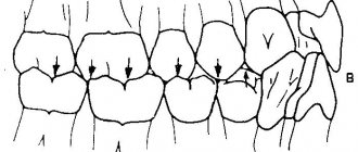
See figure 1: 1 - point Po, 2 - point Sna, 3 - point on the cutting edge of the central lower incisor, 4 - point on the top of the distal buccal cusp of the lower first molar, line (1-2) - Camper plane, line ( 3-4) - occlusal plane.
The bone Camper plane passes through the Po-Sna points. Our calculations of computed tomograms showed that in 88% of cases there are significant discrepancies between the Camper plane and the occlusal plane, i.e. they are not parallel. In 12% of the examined patients, the divergence between the occlusal and Camper planes was 15-21°.
The HIP plane (Hamulus - Incisive Papilla) passes through the hook of the pterygoid process and the interincisal papilla. In 80% of the examined patients, the discrepancy between the HIP plane and the occlusal plane did not exceed 9° (Fig. 2).
See Fig.2: 1 - Hamulus point, 2 - Incisive Papilla point, 3 - point on the cutting edge of the central lower incisor, 4 - point on the apex of the distal buccal cusp of the lower first molar, line (1-2) - HIP plane line (3-4) - occlusal plane.
The plane we found (PSIP) passes through the bony landmarks: the interincisal papilla of the maxilla and the apex of the styloid process.
The cephalometric analysis showed a coincidence in the parallelism of the occlusal plane and the plane we found in 82% with a possible discrepancy of 2°-3° (Fig. 3).
See Fig. 3: 1 - Hamulus point, 2 - Incisive Papilla point, 3 - point on the cutting edge of the central lower incisor, 4 - point at the apex of the distal buccal cusp of the lower first molar, 5 - Sna point, 6 - Po point, 7 - point (PS) at the apex of the styloid process, line (1-2) - HIP plane, line (3-4) - occlusal plane, line (5-6) - Camper plane, line (2-7) - PSIP plane .
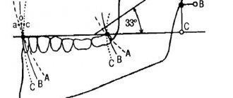
If difficulties arise in finding the direction of the styloid process, it is necessary to conduct a cephalometric analysis (Fig. 4).
See Fig.4: 1 - point Ar, 2 - point Ba, 3 - point at the base of the styloid process
We calculated that the base of the styloid process is located on the line from point Ar (Articulare) to point Ba (Basion) and on average is 0.7-0.9 cm from point Ar. The direction of the styloid process is on a line from the base of the styloid process to the irregularity at the base of the body of the mandible.
Thus, we have proposed a new method for finding the anatomical plane, which is the most accurate parallel landmark to the occlusal plane with a possible discrepancy of 2°-3°. The PSIP plane is a guideline for restoring the dentition of patients with prosthetics, which greatly facilitates the creation of individual orthopedic structures.
A method for finding an anatomical plane that is parallel to the plane of occlusion, characterized in that as a plane that is parallel to the plane of occlusion, a plane passing through the interincisal papilla of the maxilla and the apex of the styloid process is used, the placement of which is determined on a line from the Articulare point to the Basion point at a distance 0.7-0.9 cm from the point Articulare.