Rogatskin D. V. Radiologist, Ortos LLC (Smolensk)
Until recently, radiation diagnostics in dentistry was considered as an additional examination method, that is, optional, without which, in principle, full treatment could be carried out. However, in the 21st century the situation has changed dramatically, new technologies, new specialties and new requirements for the examination and treatment of patients have appeared. Currently, not a single civilized dental appointment is complete without a detailed radiodiagnostic examination of the patient, and it can be argued that radiodiagnostics in dentistry is now one of the main and most popular research methods.
The main difference between digital radiography (radiovisiography) and traditional one is that in this case, instead of film, the image receiver is a sensor that perceives radiation and transmits information to a computer. The equipment required for radiovisiography consists in sequence of a radiation source, a device for reading information, a device for digitizing information, and a device for reproducing and processing images.
Modern low-dose generators with a minimum timer value, designed to work as part of a visualization complex, are used as a radiation source. The visual imager itself consists of a sensor, which is a sensor based on a CCD or CIMOS matrix, an analog-to-digital converter and a computer program designed to optimize and store images.
At first glance, the original digital photographs may differ slightly from the usual film ones, and therefore require processing using software options. The highest quality image is the one that is closest in visual perception to analogue, therefore, even despite the highest technical characteristics of the visiograph, the quality of the final image largely depends on the capabilities of the program and the ability of a specialist to work with it.
Popular methods of radiation diagnostics
Today, the most common and popular method of radiation examination in outpatient practice is intraoral radiography of teeth, or intraoral photograph of the tooth. Sometimes intraoral photographs of teeth are called targeted, which is incorrect. A targeted photograph is a photograph taken outside the standard positioning, and standardized studies are named according to the positioning method.
At a therapeutic appointment during endodontic treatment, at least three intraoral photographs of each tooth under examination must be taken:
- A diagnostic image is necessary to assess the condition of periodontal tissues at the time of examination, make a diagnosis, determine the number and shape of roots, the direction of canals, and choose treatment tactics.
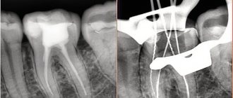
- measuring photograph - a photograph of a tooth at the treatment stage with endodontic instruments inserted into the canals with a fixed stopper length of the working part or verifiers after instrumental treatment of the canals. If the orthogonal projection is performed correctly, provided that the visiograph program is accurately calibrated and there is no projection distortion for incisors and premolars, some measurements can be taken from the diagnostic radiogram. For multi-rooted teeth, it is preferable to measure the length of the canals using endodontic instruments (Fig. 1), an apex locator or from a three-dimensional photograph.
- a control photograph is taken immediately after the end of endodontic treatment in order to determine how well the root canals are filled, as well as after a certain specified time, in order to verify the absence or detect the presence of complications (Fig. 2). When examining multi-rooted teeth and in cases where there is an additional canal, in an image taken with the orthoradial direction of the beam (direct projection), the root canals often overlap each other, which significantly complicates diagnosis and can lead to errors in the treatment process. To obtain a separate image of the root canals, radiography with an oblique (eccentric) direction of the central beam is used (Fig. 1). For each specific case, the mesial or distal inclination (angulation) of the tube in the horizontal plane is selected (for more details, see: Rogatskin D.V., Ginali N.V. The Art of Dental Radiography, 2007).
Ideally, maximum information about the topography of the roots and the condition of periodontal tissues can be obtained by performing polypositional radiography. In this case, for diagnostic purposes, three photographs are taken - one in a straight line, with an orthoradial direction of the beam, and two in an oblique projection - with a distal-eccentric (Fig. 1) and mesial-eccentric direction of the beam (respectively, straight, posterior oblique and anterior oblique projections).
The most important aspects of successful intraoral radiography are standardization and consistent manipulation. Standardization of manipulations means the ability of a specialist conducting a radiation examination to choose the optimal method for each case and take a series of identical images, regardless of the position, condition of the patient and the time separating one examination from another. That is, if a diagnostic or measurement image is considered to be of high quality, each subsequent clarifying and control image must be made with the same spatial and technical settings, and each subsequent image must be identical to the previous one (Fig. 1, 2).
Rice. 1. Diagnostic and measuring images of tooth 36, taken in direct (a) and distal-eccentric projection (b). 36 - chronic apical periodontitis (K04.5) with characteristic changes on the mesial root.
Rice. 2. A control image immediately after treatment of teeth 21, 22 (chronic periapical abscess in a state of suppuration) (a) and a delayed control image 5 months after filling the canal (b), the state of repair at the treatment stage.
Scheme for describing radiographs and fluoroscopy of the chest organs.
1) Name and age of the patient. 2) General assessment of the radiograph Method. - fluoroscopy - radiography (survey, targeted radiograph). - superexposed radiograph. - tomogram. - bronchogram. - computed tomogram. - angiogram. Indication of the organs being examined (organs of the chest cavity). Projection of the study (direct, lateral, oblique, lateroposition). Image quality (contrast, sharpness, ray hardness, correct placement). 3) Study of the lungs. Determination of the shape of the chest (regular, bell-shaped, barrel-shaped). Assessment of lung volume (not changed, the lung or part of it is increased, decreased). Establishing the state of the pulmonary fields (transparent, darkened, cleared). Analysis of the pulmonary pattern (unchanged, strengthened, weakened, deformed). Analysis of the roots of the lungs (structure, width, location, enlarged lymph nodes, vessel diameter). Functional state during fluoroscopy (respiratory movements of the ribs, diaphragm, changes in the pulmonary pattern during breathing)
Identification and description of pathological syndromes. 1) Shadow painting Blackout. Enlightenment. 2) Localization By shares By segments. 3) Dimensions in centimeters (at least two sizes must be indicated). 4) Shape: Round. Oval. Wrong. Triangular. 5) Contours Smooth or uneven Clear or fuzzy 6) Intensity Weak Medium High Calcareous density Metallic density 7) Shadow structure. Homogeneous Heterogeneous Functional signs on fluoroscopy 9) Change in the shape of a round shadow during breathing - with fluid formations (cysts). 10) Pulsation of the shadow in vascular formations (aneurysms, angiomas), etc. 11) Correlation of pathological changes with surrounding tissues: Strengthening of the pulmonary pattern in the surrounding tissues Rim of clearing around a round shadow due to pushing back adjacent tissues Pushing back or moving apart bronchi or vessels, etc. . Dropout areas.
4) Study of mediastinal organs 1) Location Not displaced Displaced (towards pathological changes in the lungs or in the opposite direction). 2) Dimensions: Not enlarged Expanded due to the left ventricle or other parts of the heart; Expanded to the right or left in the upper, middle or lower sections. 3) Configuration Not changed If changed, then this may be due to space-occupying formations of the heart, blood vessels, lymph nodes, etc. 4) Contours. Smooth Uneven 5) Functional state during fluoroscopy Rhythm of heart contractions Jerky displacement of the mediastinum during exhalation towards atelectasis, etc.
5) Study of the walls of the chest cavity. 1) Condition of the pleural sinuses: Free, Contain fluid, Have pleuro-diaphragmatic adhesions. 2) Condition of the soft tissues Unchanged Enlarged Subcutaneous emphysema is present Foreign bodies, etc. 3) Condition of the skeleton of the chest and shoulder girdle Location of bones Shape Contours Structure Presence of fused or non-united fractures. 4) Condition of the diaphragm Location is normal Displacement proximally by one intercostal space, etc. The domes have smooth contours or are deformed by pleurodiaphragmatic adhesions. Mobility of the diaphragm during fluoroscopy.
CONCLUSION RECOMMENDATIONS on the use of additional techniques. DESCRIPTION of additional techniques and methods confirmation or clarification of the previously described picture, description of newly identified pathological signs. FINAL CONCLUSION (for example, pneumothorax, parenchymal pneumonia, central exobronchial cancer without metastases, peripheral cancer, echinococcus in the unopened phase, etc.)
Methodology for describing a radiograph
Sequence of description.
1 . Assess the quality of the radiograph: contrast, sharpness, projection distortions (lengthening, shortening of the tooth), completeness of coverage of the area under study.
2. Set the image type (intraoral, extraoral, panoramic).
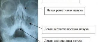
3. Determine the scope of the study: which jaw, group of teeth; When determining the jaw, it is necessary to remember some anatomical landmarks of the upper and lower jaw:
• anatomical landmarks of the maxilla
- wide chisel-shaped crowns of the upper incisors;
- intermaxillary suture (light strip) between the central incisors;
- nasal cavities;
- shadow of the nasal septum;
- orbital cavity;
— incisive foramen (at the level of the apex of the roots of the central incisors);
— rarefaction of the bone tissue of the periapical region of the upper incisors due to the imposition of the air column of the nasal openings;
- number of roots for molars (three);
— maxillary sinus (zone of clearing);
- dense shadow of the tubercle of the upper jaw behind the third molar;
— hook of the medial plate of the pterygoid process of the main bone;
- shadow of the coronoid process of the lower jaw;
· anatomical landmarks of the lower jaw:
- less dense structure of the alveolar process in the frontal region;
- shadow of the mental spine;
- narrow, long, slightly flattened roots of the lower incisors;
- shadow of the mandibular canal;
- external and internal oblique lines visible at the level of the third lower molar;
- two roots for molars;
- mental foramen, most often located under the second molar.
4.Carry out tooth shadow analysis:
a) the condition of the crown - the presence of a carious cavity, a filling, a filling defect, the relationship between the bottom of the carious cavity and the tooth cavity;
b) characteristics of the tooth cavity: presence of filling material, denticles;
c) condition of roots: number, shape, size, contours;
d) characteristics of root canals: width, direction, degree of filling;
e) assessment of the periodontal fissure: uniformity, width, condition of the compact plate of the socket: preserved, destroyed, thinned, thickened.
5. Assess surrounding tissues:
a) the condition of the interdental septa: shape, height, condition of the endplate;
b) the presence of restructuring of the intraosseous structure: analysis of the pathological shadow (area of destruction or osteosclerosis) includes determining the location, shape, size, nature of the contours, intensity, structure.
Interproximal intraoral radiography using digital technology gives a very high result in identifying primary and secondary caries. Digital radiography uses the same techniques and projections as conventional radiography. At the same time, the patient’s irradiation time is greatly reduced, and the image appears on the monitor screen almost immediately. Additionally, the computer program allows you to change shades of gray and set one color for areas of similar density.
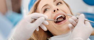
Laser fluorometry. The most advanced and at the same time easiest to use device is the Diagnodent device, produced by a German company (Fig. 1).
A laser diode creates pulsed light waves of a certain length that hit the surface of the tooth and are reflected because tooth tissue has optical properties. This reflection of light is perceived by special photocells. The carious process causes a change in the optical properties of hard tooth tissues, which fluoresce with light waves of a different length. The length of the reflected waves is analyzed by the corresponding electronics of the device and converted into digital values and an acoustic signal.
Rice. 1. Appearance of the device for laser fluorometry.
The method of working with Diagnodent is as follows:
1) the tooth surface is cleaned of soft plaque and dental deposits, which can distort the instrument readings;
2) the tooth surface is dried;
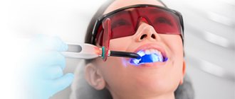
3) using a sensor, the area of dental tissue being studied is illuminated (Fig. 2), and after a few seconds the research data appears on the digital display in the form of digital indicators.
Rice. 2.
Scheme of illuminating the tooth surface with a beam of pulsed light flux for diagnosing caries. Sensing options:
a - classic;
b - a beam of pulsed light flux